How to Test a Fuse and Trace the Circuit That Blew It
In the realm of electrical systems, the ability to accurately test a fuse and trace the circuit that caused it to blow stands as an indispensable skill. Understanding the intricacies of this process not only enhances safety but also ensures the efficient functioning of electrical devices. This article delves into the methodology of fuse testing and circuit tracing, providing a comprehensive guide for both novices and seasoned professionals in the field of electrical engineering. By navigating through the fundamental principles and practical applications, readers will gain a solid foundation in these essential techniques.
Understanding Fuse Functionality and Types
Fuses are critical components in electrical systems, acting as safety devices designed to protect circuits from overcurrent conditions. They work by interrupting the flow of electricity when the current exceeds a predetermined level, thereby preventing potential damage to the circuit and associated equipment. There are various types of fuses, including cartridge fuses, blade fuses, and resettable fuses, each serving specific applications. Understanding the specifications and ratings of these fuses is crucial, as it ensures their proper selection and use within different electrical systems. Moreover, recognizing the signs of a blown fuse, such as a visible gap in the fusible link or a change in transparency, is fundamental for effective troubleshooting.
Tools and Techniques for Testing Fuses
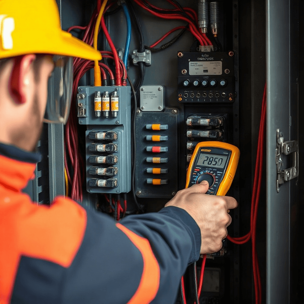
Testing a fuse requires a systematic approach and the use of appropriate tools to ensure accuracy and safety. The primary tool for this task is a multimeter, an essential device that measures voltage, current, and resistance. Before testing, it is imperative to ensure the power is turned off to avoid electrical shock. Set the multimeter to the continuity test mode and place its probes on each end of the fuse. A continuous beep or a reading close to zero indicates a functioning fuse, while an open line or no sound suggests a blown fuse. This method is efficient and provides a quick assessment of the fuse’s status, enabling timely replacements and minimizing downtime.
Identifying the Circuit Responsible for Tripping
Once a blown fuse is identified, the next step is to trace the circuit responsible for the fault. This process involves a systematic examination of the circuit components and connections to pinpoint potential issues. Begin by reviewing the circuit diagram to understand the layout and identify potential fault points. Inspect the circuit for signs of damage or wear, such as burned components or frayed wires. Utilizing a continuity tester can assist in checking the integrity of cables and connections, ensuring they are intact and free from defects. This meticulous approach aids in isolating the problematic area, facilitating targeted repairs and reducing the risk of recurring issues.
Analyzing Common Causes of Blown Fuses
Blown fuses are typically symptomatic of underlying issues within an electrical system. Common causes include short circuits, overloaded circuits, and component failures. Short circuits occur when a low-resistance path forms, allowing excessive current flow that overwhelms the fuse. Overloaded circuits, on the other hand, arise when too many devices draw power simultaneously, exceeding the circuit’s capacity. Component failures, such as faulty capacitors or transistors, can also lead to abnormal current levels, triggering the fuse. Understanding these causes is vital for implementing preventive measures and ensuring the longevity and reliability of electrical systems.
Implementing Preventive Measures for Circuit Protection
Preventive measures are essential for minimizing the occurrence of blown fuses and enhancing overall circuit protection. Regular maintenance and inspections are key strategies, ensuring that components and wiring remain in optimal condition. Additionally, installing circuit protection devices, such as circuit breakers and surge protectors, can provide an added layer of defense against electrical surges and faults. These devices automatically disconnect power during anomalous conditions, safeguarding the circuit and connected equipment. Furthermore, educating personnel on safe electrical practices and the importance of adhering to circuit load limits fosters a proactive approach to circuit management.
The Role of Technology in Advancing Circuit Testing
Advancements in technology continue to revolutionize the field of circuit testing and fuse analysis. Modern diagnostic tools, such as thermal imaging cameras and smart multimeters, offer enhanced capabilities for identifying and addressing electrical issues. Thermal cameras detect hotspots within circuits, revealing potential problem areas without direct contact. Smart multimeters, equipped with wireless connectivity and data logging features, facilitate real-time monitoring and analysis of electrical parameters. These innovations not only improve the accuracy and efficiency of testing procedures but also contribute to safer and more reliable electrical systems. As technology evolves, staying abreast of these developments is crucial for professionals seeking to optimize their approach to circuit testing and fuse management.