How to Test a P0135 Oxygen Sensor Heater Circuit Before Installing a Sensor
Diagnosing and repairing a P0135 error code related to an oxygen sensor’s heater circuit can be daunting if you are not familiar with automotive systems. This common issue can lead to inefficient fuel consumption and increased emissions, making it crucial to address. In this article, we will guide you through the process of testing an oxygen sensor heater circuit before installing a new sensor. With a methodical approach and some technical know-how, you can save both time and money by determining the root cause of the problem.
Understanding the Oxygen Sensor Heater Circuit
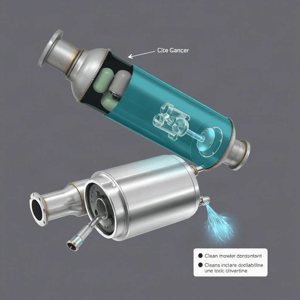
The oxygen sensor plays a vital role in monitoring the level of oxygen in the exhaust gases, helping the engine control unit (ECU) adjust the air-fuel mixture for optimal performance. In cold conditions, the sensor can take longer to reach its operating temperature. To combat this, modern vehicles use an integrated heater circuit within the oxygen sensor, allowing it to heat up quickly and function efficiently. Understanding how this circuit operates is crucial for diagnosing issues like the P0135 error code, which specifically relates to a malfunction in the heater circuit of the oxygen sensor.
Tools and Equipment Needed for Testing
Before you begin testing the oxygen sensor heater circuit, ensure you have the necessary tools and equipment. A digital multimeter is essential for measuring voltage and resistance, while a code scanner will help you confirm the presence of a P0135 error code. Additionally, having access to the vehicle’s service manual can provide specific information regarding the sensor’s wiring and location. Other useful items include a jack and jack stands for safely lifting the vehicle, and basic hand tools for accessing the sensor and related components.
Initial Diagnostic Steps
Start by confirming the P0135 error code using a diagnostic code scanner. This step ensures that the issue is indeed related to the oxygen sensor heater circuit. Once confirmed, visually inspect the oxygen sensor and its wiring for any obvious signs of damage or corrosion. Look for frayed wires, loose connections, or burnt components that could indicate an issue. If the visual inspection reveals potential problems, address these first before proceeding with further testing. It’s essential to rule out any simple causes before delving into more complex diagnostics.
Testing the Heater Circuit with a Multimeter
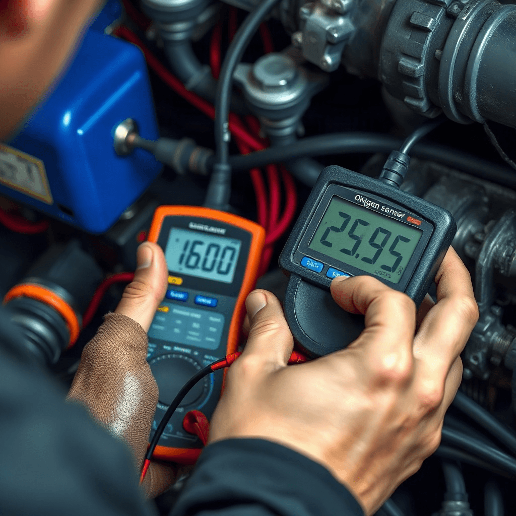
With the vehicle safely lifted and the oxygen sensor accessible, it’s time to use your digital multimeter to test the heater circuit. Start by disconnecting the sensor’s electrical connector. Set the multimeter to measure resistance (ohms) and connect the leads to the appropriate pins on the sensor’s connector that correspond to the heater circuit. A typical reading should fall within the manufacturer’s specified range, often between 5 to 15 ohms. A reading outside this range may indicate a faulty heater element within the sensor, necessitating its replacement.
Checking the Power Supply to the Heater Circuit
If the heater circuit within the sensor appears to be functioning correctly, the next step is to ensure it is receiving the proper voltage from the vehicle’s electrical system. Reconnect the sensor’s electrical connector and set the multimeter to measure voltage. Turn the vehicle’s ignition to the “on” position without starting the engine. Measure the voltage at the heater circuit’s power supply pin. You should see a voltage close to the vehicle’s battery voltage (typically 12 volts). A lack of voltage could indicate an issue with the vehicle’s wiring or a blown fuse.
Conclusion Making an Informed Decision
After conducting these tests, you should have a clearer understanding of whether the issue lies within the oxygen sensor itself or elsewhere in the vehicle’s electrical system. If the sensor’s heater circuit is faulty, replacing the sensor is the logical next step. However, if the problem stems from the power supply or wiring, addressing these issues could save you the cost of a new sensor. By thoroughly testing the system before replacing components, you ensure a more efficient and effective repair process.